
- Introduction.
- Ordered about 10 times from development boards to home-made boards
- (1) Developed on a development board with breadboard (3/9/2023)
- ②ESP32-DevKitS+ESP32-WROOM-32E 16MB (2023/4/16)
- (iii) Purchase a commercial USB-TypeC development board (8/10/2023)
- (4) (5) First attempt at developing a self-made board (8/12/2023)
- ⑥First working homemade PCB completed! (2023/9/17)
- Integration of speakers (7), (8), (9) (2023/9/27)
- (10) Struggled with ESP32 write separation (11/28/2023)
- (11) Supports LiPo charging and double-sided boards (2023/12/17)
- In retrospect.
Introduction.
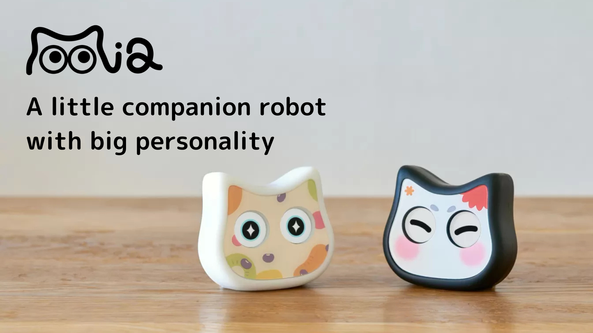
The cat-shaped talking robot “Mia” is being developed on a homemade board using an ESP32 Wi-Fi Bluetooth module.
In this article, we will summarize as a memorandum how we went from the initial development using an ESP32 development board to creating our own board and making several changes to the product.
Ordered about 10 times from development boards to home-made boards
As for the home-built circuit board, I had been involved a little in the development of an earphone-type EEG device before, but this was my first time developing a full-scale circuit board, and the requirements were different from those for the EEG, so I decided to develop it while studying analog electronic circuits from scratch.

I repeated the trial and error of my own boards from development board to product more than 10 times. Each board was left on hand and is attached.
I would like to look at them in order.

(1) Developed on a development board with breadboard (3/9/2023)
I thought I had to learn about ESP32 first, so I bought an ESP32 starter kit from Amazon, which includes an ESP32-WROVER-E development board (4MB) and a breadboard for beginners.
Basic tutorials on L-tickers, motor control, LCD displays, etc. were also included, so I studied while copying the tutorial code.
However, the Flash memory is only 4 MB, and when I put in audio files, eye image files, etc., I soon exceeded the 4 MB, so I would like to add more memory.
②ESP32-DevKitS+ESP32-WROOM-32E 16MB (2023/4/16)
I learned that Akizuki Shoten in Akihabara has a development board “ESP32-DevKitS” that allows ESP32 modules to be placed without soldering via spring pins and bought it.

In addition, there was also a Wi-Fi module ESP32-WROOM-32E 16MB at Akizuki, so the Flash memory was increased to 16MB.


Now, development is no longer a problem, but this development board has a Micro USB USB connector, and you will want to switch to a USB Type-C power supply.
Also at this time, the program was switched from Arduino to PlatformIO.
(iii) Purchase a commercial USB-TypeC development board (8/10/2023)
I bought an ESP32 development board that supports a USB-Type C power supply. However, a problem arises here.
The code I thought should work, but for some reason, it didn’t. Many of the product reviews commented that it worked fine, but for some reason, it didn’t work, so I bought another type, but it didn’t work.
I am guessing it is probably because the CC pin of the USB-typeC connector was not connected to GND via a 5.1kΩ resistor, but this is where I started to think that I needed to create my own board.

(4) (5) First attempt at developing a self-made board (8/12/2023)
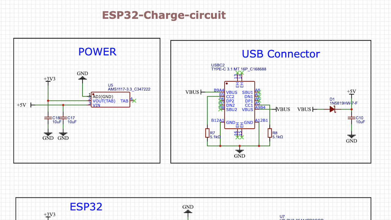
Therefore, I tried for the first time to develop my own board with a USB-TypeC power supply.
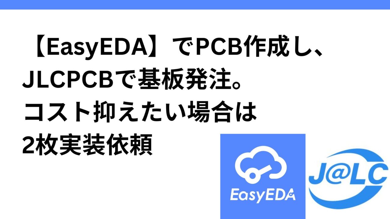
I created the circuit in EasyEDA as shown below and placed the order with JLCPCB. Incidentally, after placing the order, I learned that when requesting surface mount technology (SMT) as well, I could reduce the cost by entering 2 pieces instead of the default 5 pieces.

The received board is on the left in the figure below. Actually, this did not work due to a circuit error.
- Pin headers on both sides of the board were not specified in the PCB layout, so I had to solder them myself as shown on the right.
- The USB-UART conversion driver circuit was wrong: Rx (Receiver) of ESP32 should be connected to Tx (Transmitter) of CH340C, and Tx to Rx, but they were connected in reverse.
- EN and 3V3 were also wired incorrectly.
- AMS1117-3.3 as buck regulator and CH340C as USB serial conversion chip.

⑥First working homemade PCB completed! (2023/9/17)
Circuit errors continued to occur, and finally, on the third attempt, the first homemade board was completed!
The tweets showed his joy as he had repeatedly failed several times.


However, in the current state, wiring to the speaker, eye LCD display, and other components must be done with jumper wires, which is extremely chaotic, as shown in the figure. Therefore, the next step was to improve the board so as to eliminate the wiring.
Integration of speakers (7), (8), (9) (2023/9/27)
Around this time, I became accustomed to creating schematics in EasyEDA and began to be able to use easy-to-read notations, such as frames for each function.
However, even here, there was a mistake in the wiring with the Class D amplifier (MAX98357A), and we had to re-inject it a couple of times.

Since the number of joints with components increased, the board naturally became larger. At first, the first priority was to ensure normal operation, so resistors, capacitors, and other components were placed with as much space as possible between them.
Then, after confirming normal operation, the board was reduced in size with the same functionality.

At this point, the board and components can be directly coupled without wiring as shown in the figure below, a step forward from the chaotic state of jumper wires.

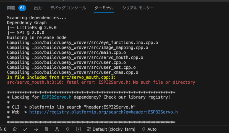
(10) Struggled with ESP32 write separation (11/28/2023)
Until then, we had included the part of writing programming code to the ESP32 Wi-Fi module, but since we wanted to keep costs as low as possible when actually shipping the product, we decided to try to separate the code-writing function.
I thought it would be easy since it was just a matter of separating them, but it turned out to be much more difficult than I had imagined. The following three articles describe how we struggled with the writing separation.
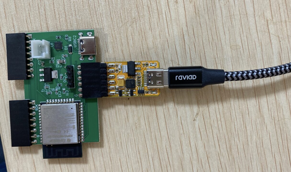
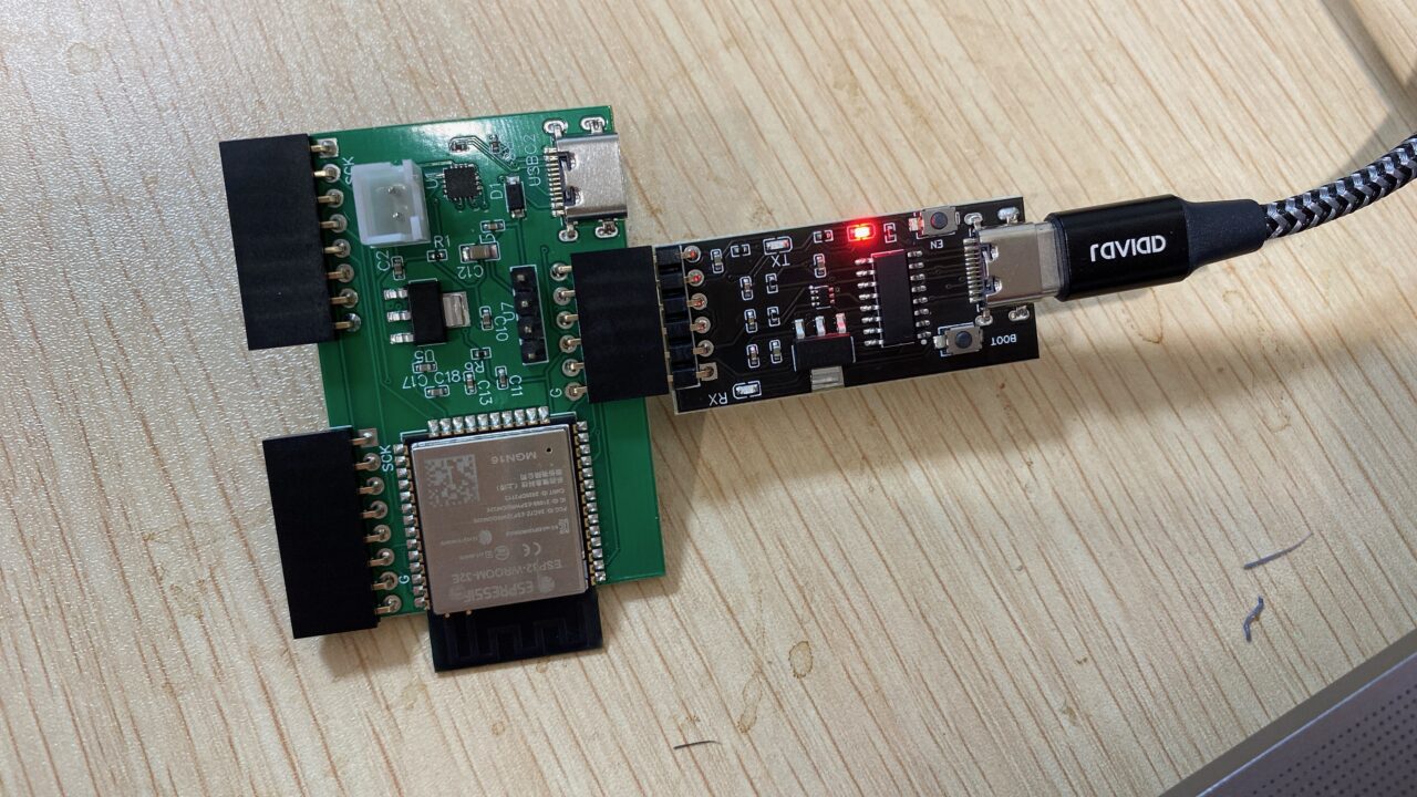
Finally, we were able to successfully separate the writing base (left side) from the rest (right side).

Schematics are shown below, respectively.


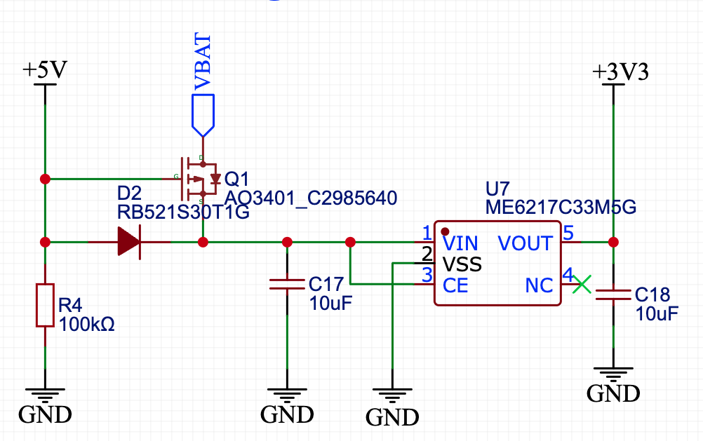
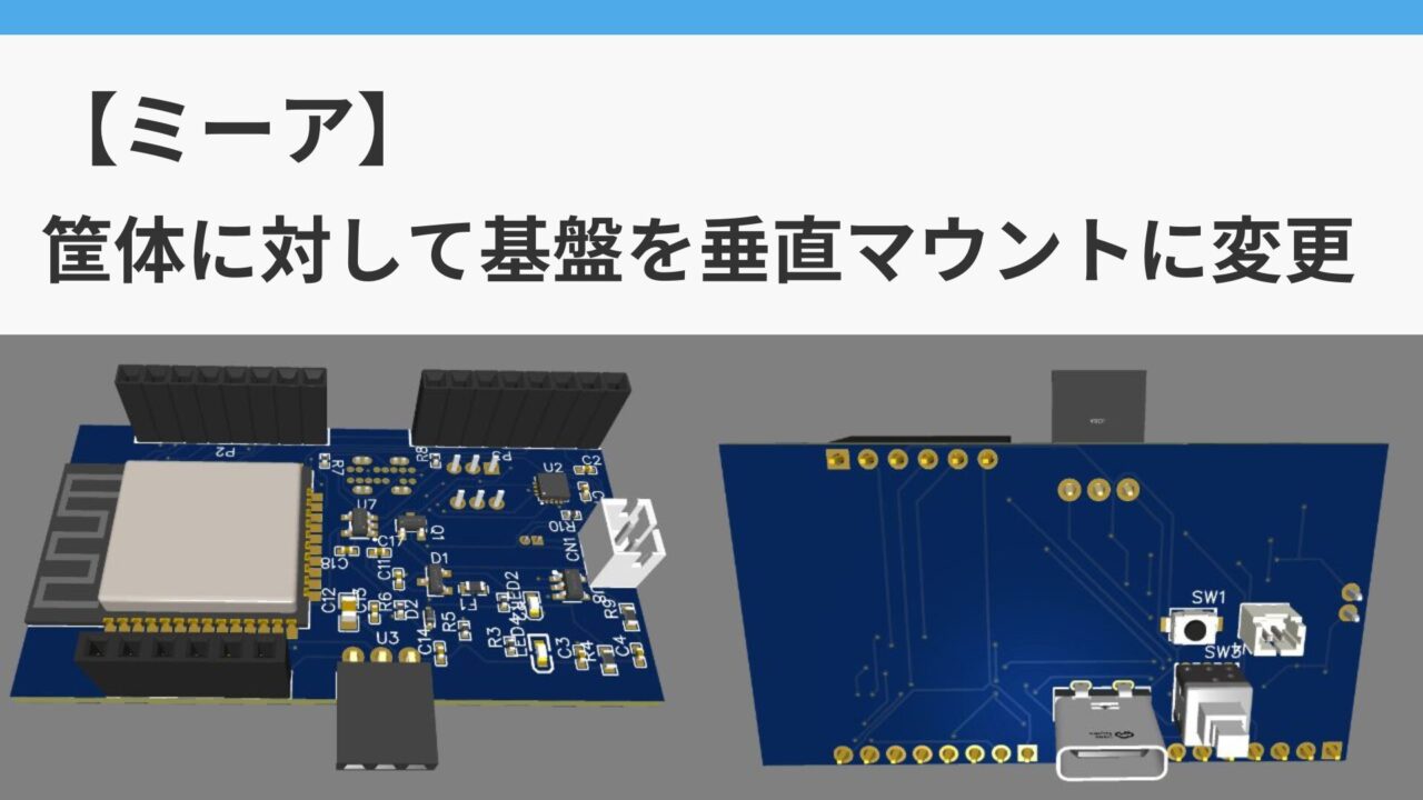
(11) Supports LiPo charging and double-sided boards (2023/12/17)
It’s almost finished, though,
- It supports a USB Type-C power supply as well as LiPo charging to make it portable
- To switch to a perpendicular arrangement with respect to the bottom of the board, making it a double-sided board and moving the power supply, speakers, etc. to the back of the board.
- Changed power supply to push-button type (latching switch)
and others were further needed and addressed.
Article on LiPo charging. I was afraid that there would be another circuit error since this is another major circuit change, but I was very happy that I was able to succeed in the LiPo compatibility in the first attempt as a result of having read the datasheet thoroughly and having done some preliminary research.
When switching from USB power supply to LiPo charging, it was necessary to use PMOSFETs, and I felt I did not have enough basic understanding, so I decided to relearn semiconductors from the basics at this time.
Latching switches installed in power circuits
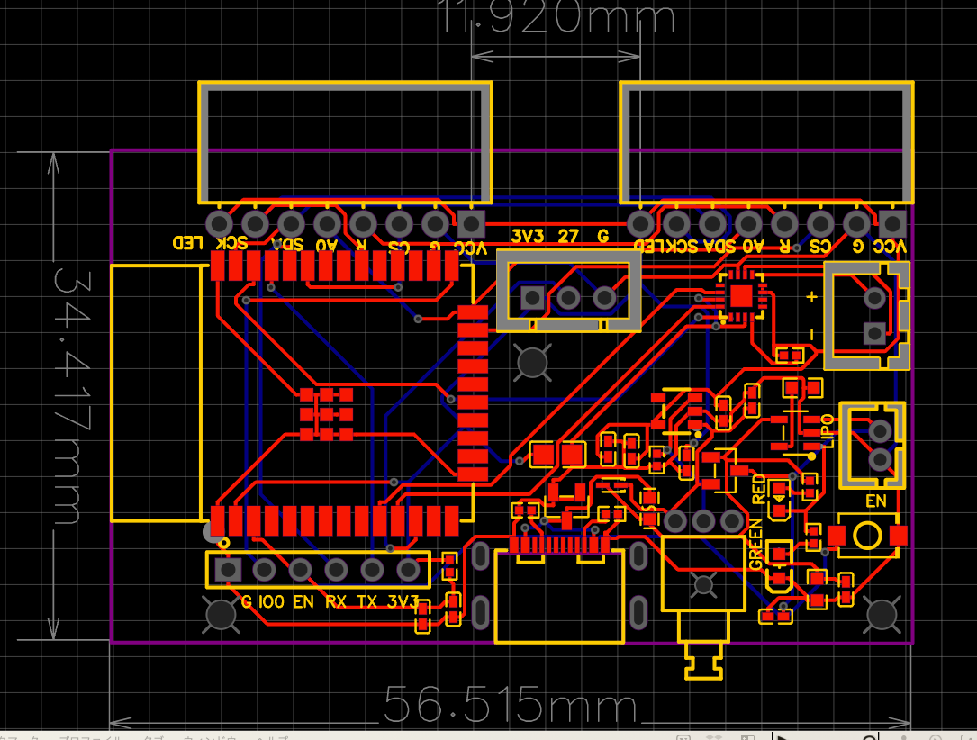
Supports double-sided substrates
The final schematic is shown here.

The substrate is here.


It is about the same size as the AirPod case and seems to have been made much smaller. Mia also looks much smaller and cuter than her initial large, slightly hokey design.


In retrospect.
It took me about five full months from the time I started developing my own board in earnest (August 2023) to the time I got it to the production version (December 17, 2023).
Since this was my first analog electronic circuit for the ESP32, I guess I had no choice in terms of speed, but I think I could have made a few more circuit mistakes and shortened the development period.
I also have to admit that JLCPCB is inexpensive (about 15,000 yen for one surface mounting) and fast (7-10 days from order to delivery), so even if there are some mistakes in the circuit, I just order the circuit once! I think that I have become so optimistic about the circuit that I have created that I have become lax in verifying whether or not it will work properly beforehand.
After trying it, I felt that, as with programming, it is important to understand the basics of electronic circuits and to read the product data sheets.
Nevertheless, I summarized with regard to semiconductors, diodes, transistors, etc., because I forget them as soon as there is a pause.


コメント