Mia, a talking cat-shaped robot that speaks a dialect, is under development.
Previously, the ESP32 OTA update function was implemented in this article.
In this case, we would like to implement firmware initialization. To allow the user to manually initialize the firmware when the ESP32 file system is corrupted due to prolonged user operation or unexpected errors.
This section also describes the use of PlatformIO and TFT_eSPI to display the status using the display in safe mode.
How to trigger initialization
With regard to initialization triggers, the following two options are possible in this case
Initialisation via MQTT
An MQTT message is sent from the application or cloud server, and the ESP32 that receives the message performs the initialization. The advantage of this method is that the device can be reset from a remote location. However, if the internet environment is not good, the reset operation may be interrupted during the process.
Hardware trigger.
A method in which a physical button or touch sensor is used to initialize the device when the user performs a specific operation (e.g. long press). The advantage of this method is that the risk of accidental initialization is low because a physical action is required.
Incidentally, Nintendo Switch defines device reset as holding down the power button for more than 12 seconds.
As we have installed a TTP223 touch sensor on Mia’s head, we would like to use it as a hardware trigger and initialize the device if the head is touched continuously for more than five seconds.
The ESP32 initialization recommended by Espressif is to reserve a factory partition for initialization in advance, separate from the two partitions for OTA updates, with the same size as the OTA updates, and keep the data for initialization there, so that when the device When resetting, the initialization data is read from the factory partition.
However, this time, the SPIFFS area has to be reserved to some extent and there is no space to prepare a new factory partition. Therefore, although it is a hardware trigger, we would like to initialize the device by specifying the initial firmware version (1.0.0) and calling the OTA update function.
Implementation steps
At the beginning of adding trigger conditions for safe modesetup() , measure the time the TTP223 touch sensor is touched, and execute safe mode if it is touched for the specified time (5 seconds) or longer.
Safe mode starts only basic system functions and does not initialize the network or database.
Specifying the firmware version
When it is detected that the touch continues for a long time, specify the initial firmware version (1.0.0) and call the OTA update function.
Perform OTA update
Download and install the specified version of the firmware.
Now, I would like to develop it in this order.
Separate safe mode with setup() function
When you press the power button to start up, if you touch the TTP223 touch sensor for more than 5 seconds, it will activate safe mode and skip the normal initialization process.
Flag inSafeModeused to indicate whether the safe mode is active. trueSet this flag in situations where safe mode is triggered.
C++
// src/main.cpp
bool inSafeMode = false;

void setup() {
  Serial.begin(115200);
  pinMode(HEAD_BUTTON_PIN, INPUT);
  Serial.println("Starting");
  print_free_heap_size("After Starting");

  // セーフモードのトリガーをチェック
  unsigned long startTime = millis();
  while (digitalRead(HEAD_BUTTON_PIN) == HIGH) {
    if (millis() - startTime > 5000) {  // 5秒以上押されていたらセーフモード
      Serial.println("Entering Safe Mode...");
      setupSafeMode();
      return;
    }
  }

  setupCommon();
  normalSetup();
}
Common setup: safe mode and normal mode
In order to maintain the basic functionality of the device even in safe mode and to be able to perform OTA updates through a Wi-Fi connection, we incorporate the initialization of NVS and LittleFS and the Wi-Fi settings into a common function.
Changed setup functions other than common setup (device shadow initialization, DB initialization, audio initialization, etc.) to not start in safe mode as the notmalSetup() function.
C++
// src/main.cpp
void setupCommon() {
    // NVSの初期化
    esp_err_t err = nvs_flash_init();
    if (err == ESP_ERR_NVS_NO_FREE_PAGES || err == ESP_ERR_NVS_NEW_VERSION_FOUND) {
        esp_err_t erase_err = nvs_flash_erase();
        if (erase_err != ESP_OK) {
            Serial.println("Failed to erase NVS partition");
            return;
        }
        err = nvs_flash_init();
    }
    if (err != ESP_OK) {
        Serial.println("Failed to initialize NVS");
        return;
    }

    // LittleFSの初期化
    if (!LittleFS.begin(FORMAT_LITTLEFS_IF_FAILED)) {
        Serial.println("Failed to mount file system");
        return;
    }
    // Wi-Fi接続
    setupWiFi(ssid, password);
}
Wi-Fi compatible: SmartConfig settings
If Wi-Fi is not connected while booting in safe mode, you will need to connect to Wi-Fi, so use SmartConfig to configure Wi-Fi connection settings.
Originally, Bluetooth was used to connect the app to the ESP32 via Wi-Fi, but when selling products that use Bluetooth, it is necessary to obtain Bluetooth SIG (Special Interest Group) certification, which increases the cost. However, it turned out that it would cost as much as $8,000, so I suddenly changed to a Wi-Fi connection using SmartConfig.
C++
// src/main.cpp
void setupSafeMode() {
  Serial.println("Entering Safe Mode: Limited functionality.");
  inSafeMode = true;

  // 共通の初期化処理を行う
  setupCommon();

  // WiFiが接続されていないか確認
  if (WiFi.status() != WL_CONNECTED) {
    Serial.println("Starting SmartConfig to setup WiFi...");
    WiFi.disconnect();
    WiFi.mode(WIFI_STA);
    WiFi.beginSmartConfig();

    // SmartConfigの完了を待つ
    while (!WiFi.smartConfigDone()) {
      delay(500);
      Serial.print(".");
    }
    Serial.println("nSmartConfig Done.");

    // WiFi接続の確立を待つ
    while (WiFi.status() != WL_CONNECTED) {
      delay(500);
      Serial.print(".");
    }
    Serial.println("nWiFi Connected.");
  } else {
    Serial.println("WiFi is already connected.");
  }
}
Separate safe mode with loop() function
loop()The function checks whether the safe mode is active, and if so, skips normal loop processing safeModeLoop()and executes.
C++
// src/main.cpp
void loop() {
  if (inSafeMode) {
    safeModeLoop();
    return;
  }

  // 通常の処理
  monitorWiFiConnectionChange();
  if (isWiFiConnected()) {
    executeWiFiConnectedRoutines();
  }
  buttonManager.handleButtonPress();
  ExpressionService::getInstance().render();
  delay(10);
}
Initialize via OTA
safeModeLoop()Now, perform an OTA update and initialize the device through a firmware update. Once initialization is complete, restart the device and proceed with the normal setup() function.
C++
// src/main.cpp
void safeModeLoop() {
  Serial.println("Safe Mode loop ...");
  upgradeFirmware("1.0.0");
  ESP.restart();
}
Use the upgrade firmware function that was previously created with the OTA update. Upgrade “1.0.0.” as the initialization version to AWS S3 in advance and specify it as an argument to the upgrade firmware function.
The upgrade firmware function is below
C++
// src/ota_update.cpp
tl::expected<void, String> upgradeFirmware(const String &firmwareVersion) {
  Serial.println("OTA firmware upgrade start");

  // ルートCA証明書を読み込む
  String cert = readRootCA();
  if (cert.length() == 0) {
    return tl::make_unexpected("Failed to load root CA certificate");
  }

  // Firmware Update URLを組み立てる
  String firmwareUpdateUrl = String(FIRMWARE_UPGRADE_URL) + firmwareVersion + ".bin";
  Serial.println("Firmware update URL: " + firmwareUpdateUrl);

  esp_http_client_config_t config = {
      .url = firmwareUpdateUrl.c_str(),
      .cert_pem = cert.c_str(),
      .timeout_ms = 600000, // 念の為に通信タイムアウトを10分に設定。
      .keep_alive_enable = true,
  };
  esp_https_ota_config_t ota_config = {
      .http_config = &config,
  };

  // OTAのエラーを格納する
  String otaError;
  int last_progress = -1;

  // OTA開始
  esp_https_ota_handle_t https_ota_handle = nullptr;
  esp_err_t err = esp_https_ota_begin(&ota_config, &https_ota_handle);
  if (err != ESP_OK) {
    otaError = "OTA begin failed: " + String(esp_err_to_name(err));
    goto ota_end;
  }

  // イメージの存在チェック(descriptionを取得)
  esp_app_desc_t app_desc;
  err = esp_https_ota_get_img_desc(https_ota_handle, &app_desc);
  if (err != ESP_OK) {
    otaError = "failed to get image description: " + String(esp_err_to_name(err));
    goto ota_end;
  }

  // OTAのダウンロードを実行
  while (true) {
    err = esp_https_ota_perform(https_ota_handle);
    if (err != ESP_ERR_HTTPS_OTA_IN_PROGRESS) {
      break;
    }
    int32_t dl = esp_https_ota_get_image_len_read(https_ota_handle);
    int32_t size = esp_https_ota_get_image_size(https_ota_handle);
    int progress = 100 * ((float)dl / (float)size);
    if (progress != last_progress) {
      Serial.printf("Firmware update progress: %d%%n", progress);
      last_progress = progress;
    }
  }

  // OTAが正常に完了したか確認
  if (err != ESP_OK) {
    otaError = "OTA finish failed: " + String(esp_err_to_name(err));
    goto ota_end;
  }

  // OTAで完全なデータが受信されたか確認
  if (esp_https_ota_is_complete_data_received(https_ota_handle) != true) {
    otaError = "OTA image was not completely received";
    goto ota_end;
  }

  // OTAの終了処理を実行
  err = esp_https_ota_finish(https_ota_handle);
  if (err == ESP_ERR_OTA_VALIDATE_FAILED) {
    otaError = "OTA image validation failed";
    goto ota_end;
  }

  Serial.println("Firmware upgrade succeeded");

  return {};

ota_end:
  esp_https_ota_abort(https_ota_handle);
  return tl::make_unexpected("OTA process ended unexpectedly: " + otaError);
}
Show initialization status on eye display
With the above, it is now possible to safely separate the processing in safe mode from the normal startup processing.
However, regarding Wi-Fi connection, if Wi-Fi connection is not possible in safe mode, there is no way to notify the user, so the status at the time of starting safe mode is displayed on the eye LCD display (ST7735s is used). I’ll do what I do.
The TFT_eSPI library is used to draw the LCD display.
Customize TFT_eSPI settings with PlatformIO
Actually, in the development of safe mode processing, I was most hooked on the part where the status is displayed as text on the LCD display, but since I am writing it in VSCode with PlatformIO instead of Arduino, I wrote the following in platformio.inithe file section. build_flagsIt was necessary to set it to.
C++
// platformio.ini
[env]
platform = espressif32
framework = arduino
board = esp32dev
lib_deps =
    bodmer/TFT_eSPI@^2.5.34

build_flags =
    -DUSER_SETUP_LOADED=1
    -DLOAD_FONT4
    -DSMOOTH_FONT
When editing the default settings of the TFT_eSPI library, it User_Setup.his recommended to directly modify the custom settings file in the Arduino IDE. However, this time, since we are developing with PlatformIO and the User_Setup.h file itself has been deleted, we need to make custom settings in platformio.ini.
↓User_Setup.h file of TFT_eSPI library
DUSER_SETUP_LOADED=1
- This definition
User_Setup_Select.htells the TFT_eSPI library to ignore (the settings in) the default configuration file and use project-specific settings. ThisUser_Setup.hallows custom settings to be injected at compile time without physically editing or rewriting the .
DLOAD_FONT4
DLOAD_FONT4tells you to load a particular font provided by the TFT_eSPI library (in this case font 4) for use in your program.- Fonts other than 4 (1,2,4,6,7,8) can also be specified. For more information, see the User_Setup.h file in the TFT_eSPI library.
At first, I forgot to specify this specific font size and was specifying the font size only in the code, so when I built it, the characters were not drawn and I couldn’t figure out the cause, so I spent about 2 hours. It’s gone….
DLOAD_FONT4 does not mean 4px, it is just the font size specified by the TFT_eSPI library. There are font sizes other than DLOAD_FONT4, so adjust them accordingly depending on your display and the number of characters you want to display.
DSMOOTH_FONT
DSMOOTH_FONTFlag enables the smooth font feature of the TFT_eSPI library. The characters will still be displayed without it, but it will improve the readability of the text. Useful when clear text display is required on a small display.
Creating text display function for LCD display
After setting the above settings in the platform.ini file, create a text display function.
The talking cat robot we are currently developing uses two LCD displays for each of the cat’s eyes, and we want to display the same text on both displays, so we set the chip select (CS) pin of each display as an output. , LOWactivate the display by setting it to low voltage ( ).
displayText()The function displays the specified message on the display.
- Set text :
tft.setCursor(10, 30, 4). Use it to set the cursor position and specify the font size of the text. The first argument is the X coordinate, the second argument is the Y coordinate, and the third argument is the font size. This 4 corresponds to DLOAD_FONT4 set in build_flags in the platform.ini file. If you want to set a smaller font size (such as 2), enter 2 and specify DLOAD_FONT2 in build_flags. - Display Message :
tft.println(message)Calls to display the specified message on the display. By default, the println function wraps horizontal characters when they reach the edge of the device and displays a new line. - Finish drawing :
tft.endWrite()Call to end the drawing process anddigitalWrite(eye[e].tft_cs, HIGH)return the CS pin to high voltage to end the display operation.
C++
// セーフモードでのディスプレイ初期化
void initSafeModeDisplay() {
  Serial.println("Initializing display for Safe Mode...");
  pinMode(TFT1_CS, OUTPUT);
  digitalWrite(TFT1_CS, LOW);
  pinMode(TFT2_CS, OUTPUT);
  digitalWrite(TFT2_CS, LOW);

  tft.init();
}

void displayText(const char* message) {
  Serial.println("Display safemode message called ...");
  for (uint8_t e = 0; e < NUM_EYES; e++) {
      digitalWrite(eye[e].tft_cs, LOW);
      tft.startWrite();
      tft.fillScreen(TFT_BLACK);
      tft.setCursor(10, 30, 4);
      tft.setTextColor(TFT_WHITE);
      tft.println(message);
      tft.endWrite();
      digitalWrite(eye[e].tft_cs, HIGH);
  }
}
Display status text in safe mode
Finally, call the created displayText() in safe mode.
C++
void setupSafeMode() {
    Serial.println("Entering Safe Mode: Limited functionality.");
    inSafeMode = true;
    initSafeModeDisplay();
    displayText("Safe Mode Active");

    // 共通の初期化処理を行う
    setupCommon();

    // WiFiが接続されていないか確認
    if (WiFi.status() != WL_CONNECTED) {
        Serial.println("Starting SmartConfig to setup WiFi...");

        // WiFi接続を初期化
        WiFi.disconnect();
        WiFi.mode(WIFI_STA);
        WiFi.beginSmartConfig();
        displayText("WiFi Initialiezd");

        // SmartConfigの完了を待つ
        while (!WiFi.smartConfigDone()) {
            delay(500);
            Serial.print(".");
            displayText("SmartConfig Setting");
        }
        Serial.println("nSmartConfig Done.");


        // WiFi接続の確立を待つ
        while (WiFi.status() != WL_CONNECTED) {
            delay(500);
            Serial.print(".");
            displayText("WiFi Connecting");
        }
        Serial.println("nWiFi Connected.");
        displayText("WiFi Connected");
    } else {
        Serial.println("WiFi is already connected.");
        displayText("WiFi is already connected");
    }
}


void safeModeLoop() {
  Serial.println("Initializing device...");
  displayText("Initializing device...");
  upgradeFirmware("0.1.13");
  displayText("Initialization complete");
  ESP.restart();
}
Operation confirmation
At startup, press the TTP223 touch sensor for more than 5 seconds.
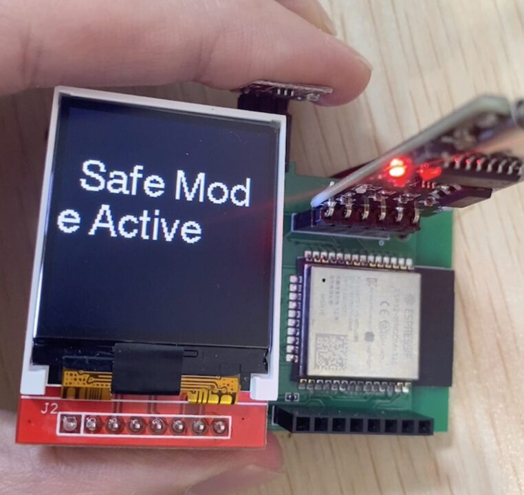
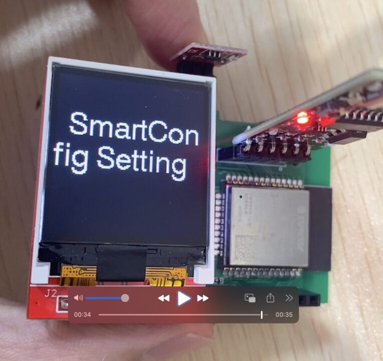
The computer will then enter safe mode and the words “Safe Mode Active” will appear on the LCD display. After that, it will automatically try to connect to Wi-Fi, and if Wi-Fi is not connected, the words “SmartConfig Setting” will be displayed.


If the words SmartConfig Setting are displayed, the user launches the ESP touch app and connects the app to the ESP32 via Wi-Fi. In the ESP touch app, a completion message will be displayed when the connection with the ESP32 is completed.


ESP32 can be updated directly via OTA. When the OTA update is complete, the message “Initialization complete” will be displayed.


ShellScript
12:34:02.416 > Starting
12:34:02.416 > After Starting - Available heap size: 243100 bytes
12:34:07.418 > Entering Safe Mode...
12:34:07.418 > Entering Safe Mode: Limited functionality.
12:34:07.423 > Initializing display for Safe Mode...
12:34:08.642 > Connecting to WiFi with SSID and password from build flags...
12:34:08.651 > WiFi connecting ...
12:34:38.652 > WiFi connection failed
12:34:38.653 > Starting SmartConfig to setup WiFi...
12:34:38.655 > WiFi Disconnected.
12:34:39.240 > ................................................WiFi Connected.
12:35:04.744 > IP Address: 192.168.XX.XXX
12:35:05.019 > .......
12:35:08.282 > SmartConfig Done.
12:35:08.282 >
12:35:08.282 > WiFi Connected.
12:35:08.314 > Initialize Firmware ...
12:35:08.349 > OTA firmware upgrade start
12:35:08.378 > Firmware update URL: https://XXX/1.0.0.bin
12:35:09.284 > Firmware update progress: 0%
12:35:09.920 > Firmware update progress: 1%
12:35:10.426 > Firmware update progress: 2%
...

12:36:26.589 > Firmware update progress: 99%
12:36:26.859 > Firmware update progress: 100%
12:36:28.469 > Firmware upgrade succeeded
12:36:28.512 > WiFi Disconnected.
12:36:30.134 > WiFi connecting ...
12:36:30.276 > WiFi Connected.
12:36:30.277 > IP Address: 192.168.XX.XXX
12:36:30.334 > WiFi connected
12:36:35.372 > Initialise eye objects
12:36:35.372 > Create display #0
12:36:35.375 > Create display #1
12:36:36.309 > Initialise Audio
After that, the ESP32 will reboot and return to normal operation.


