Introduction.
In the previous article here, we simulated a series of steps up to the packing of the mia.
Now, I will also fix the firmware write version of the production and actually assemble it.
Bring parts to the rental room
This time, we will be working in a rental room, not at home, so we pack the necessary parts in a large carry case and head to a nearby rental room. I was like a person who is about to travel abroad.


Arrange parts in order of assembly process
I arrived at the rental room at 10 am. I rented the room for three hours until 1:00 PM.
Since the complete tear down is at 1:00 p.m., the actual assembly time is about 2 hours and 45 minutes.
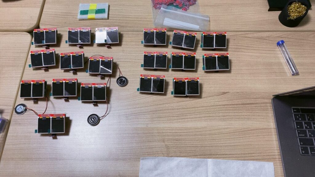
First, the parts are arranged in the order of the assembly process.

Start of assembly
Touch sensor and speaker installation
On the left is the board with the touch sensor and speaker already installed, and on the right is the board with the touch sensor and speaker not yet installed. The first step is to bring it from the right to the left.
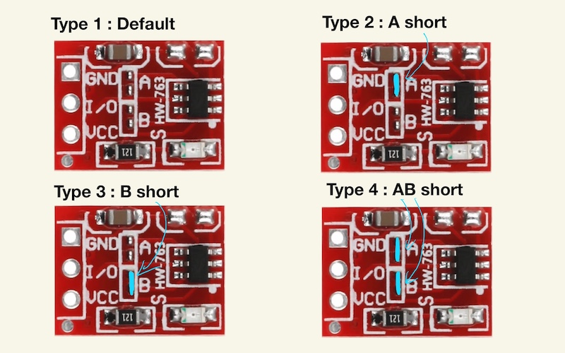
To attach the touch sensor to the board, cut the male pin headers with nippers so that they have three pins each. To prevent them from flying off when cutting, cover them with one hand while doing so.
Then, solder the touch sensor and pin headers.


Here is the touch sensor with pin header.
Cut the end of the pin header with nippers to prevent it from hitting the top of the enclosure (to prevent it from hitting the enclosure)


Finally, use a glue gun to attach and secure the touch sensor to the board. Also, attach the speaker terminals to the back of the board.


Also, a button to cover the power switch will be installed.

Board Screwed
First, the speaker is placed at the rear of the enclosure, and the board is placed at the rear. Since the speaker conductors are long, they should be placed around the top of the enclosure. We found that extending the speaker wiring at a 45-degree angle to the right of the chassis was sufficient to keep it in place without bending.

Incidentally, in the figure below, the speaker wiring comes out at a 45-degree angle to the upper right, so when the board is placed, it deflects a little as shown in the lower right figure.


Screw the board in two places with M2 screws.


After screwing in, install two LCD displays corresponding to the eyes.

Install the enclosure front and screw it down.
Wipe off any dust on the LCD display surface and remove the protective cover


Beautiful! (I know, I know, don’t say that to yourself.)

Fit the front panel and screw it in place with three M3 screws.


Here is the finished state.
It’s starting to look pretty much like that! So far, about an hour and a half has passed for 18 pieces.

When I checked the operation, I didn’t expect it to work!
At this point, I’ll try to power it up with a USB TypeC power supply and see if it actually works.
Well, it will all work! I thought it would, but no way, “Almost half of it doesn’t work! “
When working properly, it looks like the following (the protective sticker on the surface of the acrylic panel has not been removed yet, so the ochre-colored front panel is still there)

But I found something like this that doesn’t have glowing eyes

There are three possible causes
- Touch sensor is too far away and not responding.
- Board is not written correctly.
- Defective surface mounting on board
To determine the cause, we decided to unscrew it again to verify the cause. It is not a simple matter.
Actual verification revealed that most of the causes are touch-sensitive.
The touch sensor of the TTP223 is a capacitance sensor and catches changes in capacitance even if the distance is about 5-6 mm away, but perhaps there is some variation in the components, or the distance is slightly too far, or the touch sensor does not respond when it is viewed from right beside and falling toward the front However, when viewed from the side, the touch sensor would not respond if it fell forward.
So, push up by hand so that the angle between the pin header and the touch sensor is obtuse instead of acute.

Interference between capacitance sensor and speaker wiring
This made some of them work properly, but on the other hand, some of them now show a QR code on the display, and the logic is that the QR code is necessary for the Wifi connection with the app, and it appears after a certain number of seconds when you press and hold the code by hand.
The fact that the QR code is displayed means that the touch sensor is turned on all the time, and I thought there seemed to be no cause that I could think of, but then I thought, no way, the speaker wiring runs near it (since it was assembled that way), so it must have recognized the speaker wiring as a conductive material and turned on all the time. I thought it might have turned ON.
The speaker wiring is made of metal and is conductive because audio signals flow through it when it is turned on and energized. This likely affected the touch sensor always ON.
So, from the suspicious situation on the left, we changed the speaker wiring so that it passes under the touch sensor as shown on the right, and now they also work properly!


Defective surface mounting around power circuits
However, out of the 18 units assembled, one unit had what appeared to be a defective surface mounting on the board. When the writing board is removed, power is also supplied to the LCD display when the power is turned on, causing the LCD display to light up. However, when the power is turned on with USB Type C power supply without the writing board, the LCD display does not light up to begin with.
There seems to be a surface mounting defect around the power circuit (surface mounting is done by JLCPCB). Since there is nothing we can do about it (it would be too much work to check and correct continuity of all components), we will classify them as defective. (It is too much work to check all the parts for continuity and correct them.


Remove protective sheet and bag
The normal operation of 17 meers, excluding 1 defective meer, was successfully confirmed.

Finally, remove the protective sheet from the front acrylic panel, wipe the area around the enclosure clean with an alcohol surface, and place it in the transparent sheet.


Completion!
We managed to get this far: 17 pieces took about 2.5 hours for two people to assemble. We found some areas in the assembly process that could be made more efficient, so we plan to assemble them a little more efficiently next time. In the end, we need to assemble 100 pieces.

Finally, paper packing is laid on the cardboard and the instruction manual is placed on top to complete the process.
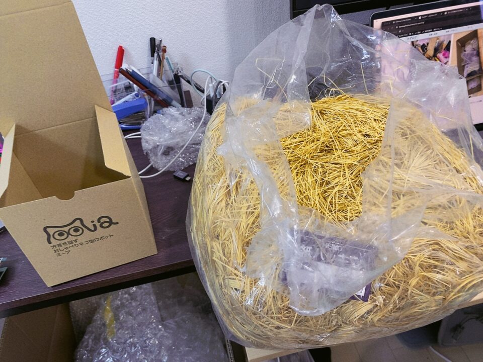
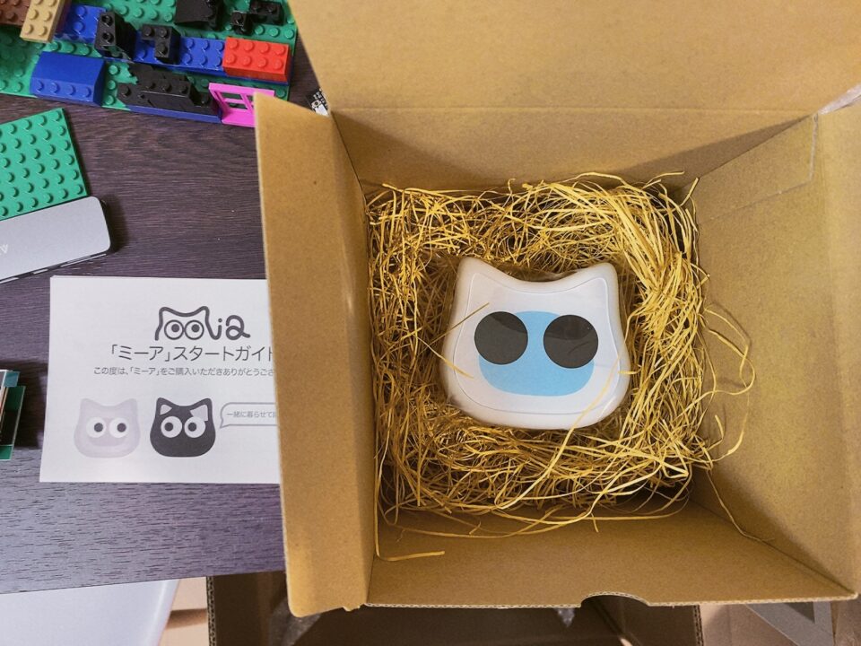
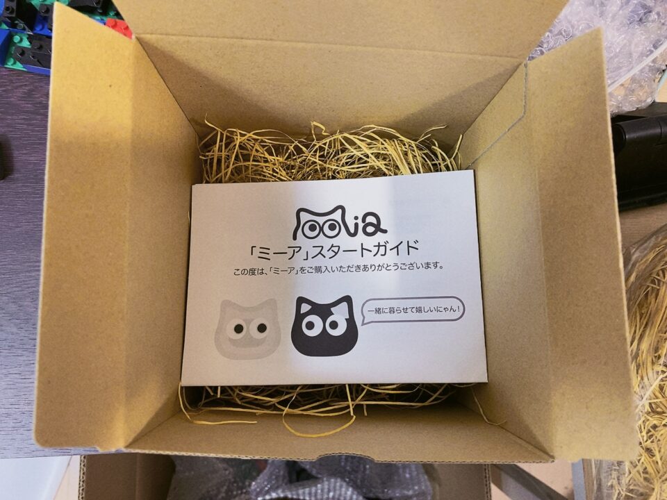
So, I have successfully completed the assembly with the acrylic panel and will release it this evening or night. I am so excited!
P.S. You can purchase from this site.
