Introduction.
Developing “Mia,” a talking cat-shaped robot that speaks various dialects.

In this article, we changed the IC package of the Class D amplifier from TQFN to WLP, and 4 out of 25 were defective in the following areas around the speaker.

- 1 piece: No sound plays at all.
- 3 pieces: Sound cracking
- 1 piece: LCD display does not light up (power is not supplied to the LCD in the first place)
Since the remaining 20 units are operating normally without incident, we could clean up the problem with a surface mounting error on the JLCPCB (we actually submitted a Quality Complaint), but if there are parts that can be prevented around the circuit wiring, we think it is better to address them and attempt to take countermeasures.

After a Quality Complaint to the JLCPCB…
Click here to learn how to file a Quality Complaint on the JLCPCB website.

After a Quality Complaint to the JLCPCB, the following response is here.
Hello sir or madam, I’m sorry.
Thanks for reaching out and we are sorry some boards do not work well.
C2682619 is a BGA component and we had X-ray inspection at that time. The inspection result is all well and the solder joints should be OK.
If there is any misalignment or any abnormality that may cause the problem? If yes, kindly share us some close-up images for a check.
Best regards,
I then sent them a video of the defective product as well.
Hello there,
Thanks for your reply.
It seems the screen and the speaker were not provided from our side. Would it be possible they were not well?
If customer considers the root cause is C2682619, could you try to resolder it for a check? We would like to know the root cause and try to avoid it in future production.
Thanks in advance.
Best regards,
So, if there is indeed a deficiency in surface mounting, I am salty to send photographic evidence of that area.
Investigation of the cause of sound crackling
Verify if sound crackling can be resolved by lowering the volume with the application.
First, since the crackling could be due to the input voltage to the speakers being too high, the application was used to lower the volume as much as possible to see if the crackling could be eliminated.

This one was not particularly different and sounded cracked.
Using a magnifying glass, visually check for wiring defects
Next, visually check for wiring defects.

Visually check that the nine wires coming from the I2S digital amplifier (Max98357a WLP) are firmly connected, using a magnifying glass to compare them with the normal board.
For example, here is the wiring that connects pin 25 of the ESP32 woom32E module to the digital amplifier LRCLK


I visually checked all the wiring and there seemed to be no flaws at a quick glance.
Inadequate wiring around power supply?
When I connected a board with sound cracking to a usbc write board and played audio, the usb to ttl ch340c was hot.

So, I thought there might be a wiring defect around the power supply (overcurrent or ripple or noise in the power supply line), but this also seems to be OK as far as visual checks are concerned.
Voltage measurement using oscilloscope
Further verification would require using an oscilloscope to measure the voltage at each point.
About two years ago, I decided to pull out and use this oscilloscope that I had used for board verification of an earphone-type EEG service I was developing at the time.


Calibration setting with the manual
There were also explanatory videos on how to measure voltage, current, resistance, and capacitance of capacitors

Some boards do not play sound at all, so use an oscilloscope mainly to check power supply, I2S signals, and outputs
1. check if 3.3V power supply voltage is supplied at the VDD pin.
2. check if the I2S signals on the BCLK, LRCLK, and DIN pins are operating correctly and check the waveforms with an oscilloscope.
3. check if the output signals on OUTP and OUTN are generated correctly and check the waveforms.
4. check if the SD_MODE# pin is set correctly.

But when I was checking, I mistakenly short-circuited one of the IC packages on the normal board for comparison, and one of the IC packages became unusable. (Crying).
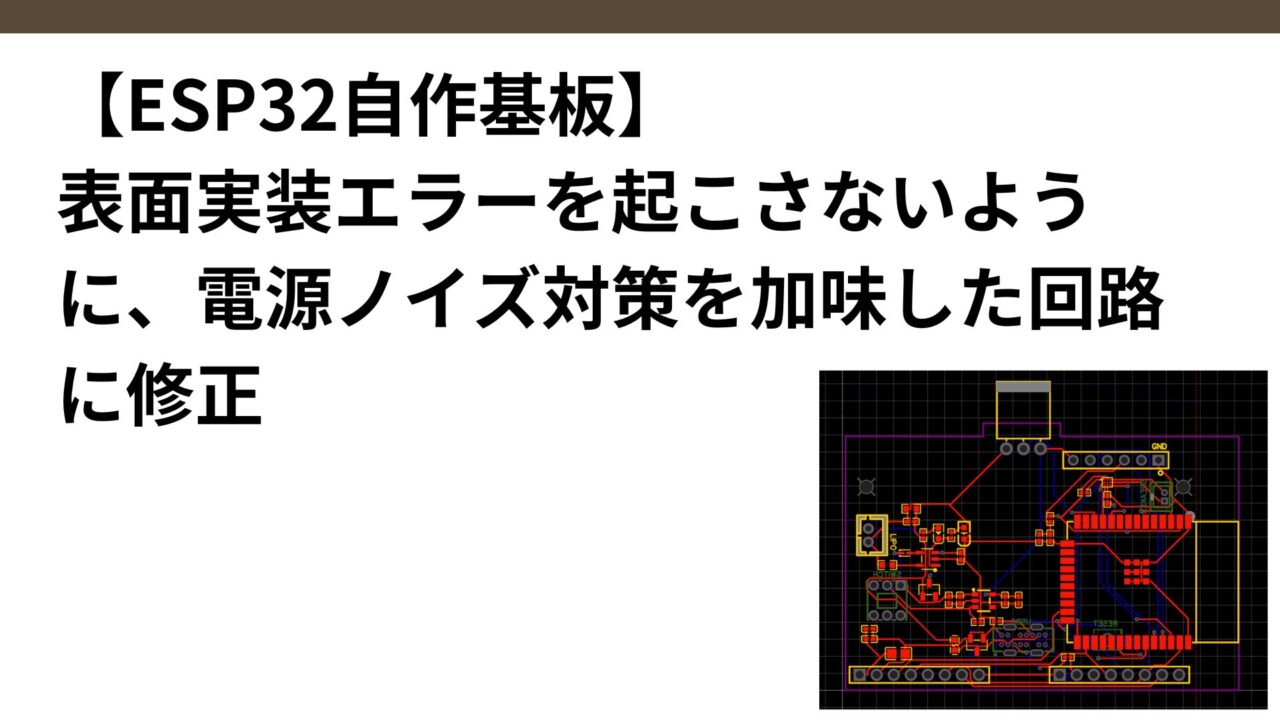
I’m getting a little scared, so I’m going to stop investigating the cause and modify the circuit (specifically, move the components around the I2S amp closer together and take measures against power supply noise) to make surface mounting errors as unlikely to occur as possible.
Click here to read the article on circuit modification.