Introduction.
Developing “Mia,” a talking cat-shaped robot that speaks various dialects.

In the previous article here, I tried to investigate the cause of the defective board, but gave up in the process, so I tried to continue.
Voltage measurement method for boards (component-to-component and wiring)
When we asked the tech staff at TiB FAB, a demonstration field where prototypes can be built and products prototyped, how to investigate the cause, they told us that there are two ways
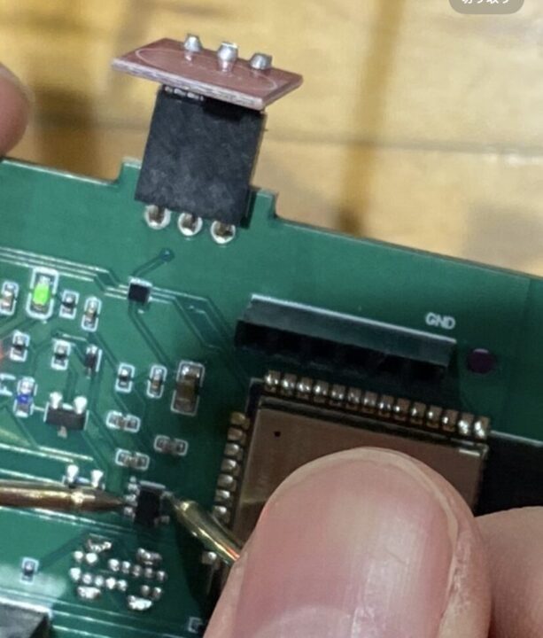
1) Measuring the voltage between components: Measure the voltage by placing the tip of the oscilloscope probe on the soldered component land area.
(2) Measuring the voltage of wiring: Since the wiring on the board is often covered with resist (insulation layer), voltage cannot be measured by applying a probe over the wiring as it is. At this time, to avoid damaging the wiring, the cutting edge of the cutter should be level with the board, and then lightly cut horizontally. Then, the probe is placed in contact with the exposed copper foil and the voltage is measured.
First, measure the voltage between components and proceed to investigate the cause.


Identified 6 patterns causing board defects
It took quite a bit of time, but we were able to disassemble 11 defective boards out of the 150 boards we have ordered so far into the following 6 patterns.
Power failure problem
- IC (Fuse) mount defective: 2 pcs.
- Inadequate USB mount: 1 pc.
- Incomplete buck regulator (ME6217) mount: 1 piece
- Sensitivity failure of latching switch: 1 pc.
Problem of not being able to write code
- TXRX error: 1 piece
Causes of no sound or broken sound
- IC (MAX98357A) mounting error: no sound or broken sound: 5 pcs.
Each will be looked at in detail.
Inadequate buck regulator (ME6217) mount
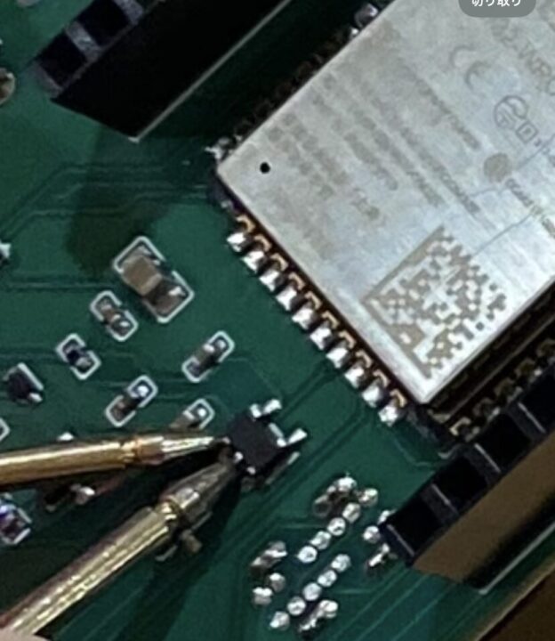
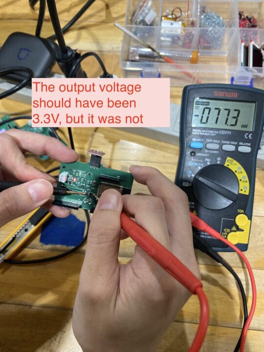
The 5V power supply from USB is stepped down to 3.3V with a step-down regulator to drive the ESP32. Of the ME6217 components in the circuit diagram below, the difference between pin 3 and pin 1 (input voltage) must be 5V and the difference between pin 3 and pin 5 (output voltage) must be 3.3V.


However, when actually measuring, the input voltage is correct at 5V, but the output voltage is 0V instead of 3.3V. This is either because the ME6217 component itself is broken or the ME6217 is surface mounted.
As for this one, I actually inquired about it at the JLCPCB’s Quality Complaint.

IC (Fuse) mount inadequate
The fuse, which is used for the purpose of preventing equipment from becoming dangerous due to overcurrents caused by abnormal conditions in electrical circuits (e.g., short circuits and overloads), must have a voltage of 5 V back and forth on the circuit.


However, when I actually measured it, I found that it was 0V instead of 5V on one of the fuse lands. This is due to the mounting of the fuse.

USB mount defective
The power supply from USB is 5V, so the wires extending from VBUS must be 5V.

The voltage between VBUS and GND was 5 V as shown in the left figure below for the normal board, but 0 V as shown in the right figure below for the defective board.


TXRX error
This one does not start writing when the code writing board is connected, and if it is normal, both TXRX blinks on the writing board side, but in the defective one, only RX blinks.

When I try to start writing, the writing does not proceed.

Thinking that there might be a possibility of poor contact between the writing board and the main unit’s board, I tried shaving the female pin header on the main unit side with nippers to expose it and squash any possibility of poor contact, but the result was the same.
Probably an error such as a broken wire between the TXRX of the main unit and the TXRX of the ESP32.

Latching switch sensitivity failure
This is a problem where the latching switch sensitivity is defective and the power on/off does not work smoothly, although it works normally. Although it works, we are hesitant to ship it as a product in this condition.

IC (MAX98357A) mount error
This is a defective product with no sound or cracked sound that occurred after the Class D amplifier was changed from the 16-pin package used in the initial lot to a smaller 9-pin package.
Although the cause of this problem has not been firmly identified, we have at least confirmed that the voltage on the IC is normal at 3.3V.

Next Step: Substrate Rework
Now that we have been able to isolate some of the causes, the next step is to rework what can be reworked.
Reworking the MAX98357A WLP package, which is the cause of the wiring error (TXRX) and crackling/no sound, is judged to be difficult because the component is too small. Also, regarding the USB-C connector, it seems difficult because it has 14 pins.
So, the things that could be done are
- buck regulator
- fuse
- latching switch
Three of the three. I have never done rework in earnest, so I will ask the tech staff about it the next time I go to TiB FAB.
Started serial printing service at JLCPCB
In this case, analog management was conducted by placing a sticker on the back of the board with the details of the defective product.

However, I think this is a recent start, but JLCPCB allows serial numbers to be put on boards (free of charge), so I would like to try serial printing in the future as a way to manage board status.

In the future, when we have defective products, we would like to keep data on the details of the defective products along with serial numbers in a spreadsheet.
