
Currently developing “Mia,” a talking cat-shaped robot that speaks dialects.

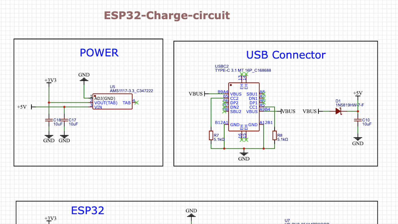
Here is Mia’s current ESP32 homebrew board circuit.

It is designed to be powered by USB TypeC, but conversely, it will not work unless the ESP32 is constantly connected to USB.
So this time, I would like to add a LiPo circuit so that it can be powered from a LiPo battery. The LiPo battery is used here.
LP552036: rated voltage is 3.7V, standard capacity (= maximum capacity): 360mAh

About Lipo Batteries
Lipo Battery Characteristics
The characteristics and conditions of Lipo batteries are as follows
- The rated voltage is 3.7V, and the battery is charged to about 4.2V when fully charged (Lipo used in this case is charged to 4.28V). 3.0V or higher is sufficient to start charging.
- It will break down if a voltage of 4.2V or higher is applied.
- Voltage drops during discharge; safe discharge limits typically range from 3.0V to 3.2V; below 3.0V, it breaks down
- Protection circuits are required to prevent overcharging and over-discharging.
Lipo charging circuit: uses MCP73831 chip
The MCP73831 uses a constant voltage power supply of 3.75~6 V. It can also be charged from a VBUS (5 V) power supply at the USB terminal.
Click here to see the charging circuit in the datasheet.

Click here for data sheet
The description of the terminals used in this project is as follows

Charging current: Basically 1C charging. 1C or less is OK.
LiPo batteries should be charged at 1C. 1C charging means charging at a current equal to the capacity of the battery. For example, a 1000mAh battery should be charged with a charging current of 1A. In this case, the battery is a 360mAh battery, so it is charged with a charging current of 360mA.
Why is 1C charging basic?
- LiPo batteries require accurate charging and discharging, especially avoiding overcharging and over-discharging. Excessive charging currents and fast charging can generate excessive heat in the battery, increasing the risk of overheating and ignition. So 1C charging is one of the basic guidelines for safe battery charging.
- However, doing so at less than 1C is not a problem. In fact, it is often recommended to use slower charging rates (e.g., 0.5C or 0.2C) to extend battery life. This places less stress on the battery and may improve long-term performance. The downside is longer charging times.
In this case, since the charge speed and maximum charge current for 1C charging are the same at 360 mAh, the circuit should be designed so that this charge current speed is not exceeded.
Charging current is regulated by PROG.
The charging current rate can be regulated by a resistor connected to the PROG pin of the MCP73831 chip.
The MCP73831 supports charge currents from 15 mA up to 500 mA.

The charging current is inversely proportional to the resistance and is expressed by the equation IREG (charging current: mA) = 1000V / Rprog (kΩ).
In this case, the maximum charge current rate is 360mAh, so the requirement is Rprog > 1000/360 = 2.77…kΩ.
In this case, I set Rprog=3kΩ. There was no specific mention in the Datasheet about the required resistance error for the prog, but I used ±1%, which is generally required for batteries.
Since the pitch interval of the LiPo battery was 2mm, the following connectors were selected for connection

Click here to see the circuit created.

LED visualization of charging status
In this case, since we want to visualize the charging status, we will use the STAT pin to indicate the charging status.
Designed so that the [Charge] lamp (red LED) lights up when charging is taking place and the [Ready] lamp (green LED) lights up when charging is complete.
The STAT pin is connected to an LED that indicates the charging status. When a LiPo battery is connected and charging from the USB terminal, the STAT pin is at a low voltage (near 0V) and LED2 (red) lights up. When charging is completed, the STAT pin becomes high voltage and LED4 (green) lights up.
Because the STAT pin is low during charging, there is not enough voltage differential across LED4, and therefore it does not light up. For a typical green LED, the forward voltage (forward voltage: the minimum voltage required for the diode to start conducting and for current to flow) ranges from about 2.0V to 2.2V.
How to supply power to ESP32?
Switching voltage regulator from AMS1117 to ME6217 series
Until now, the ESP32 has been powered by a 5V power supply connected to USB and using the AMS1117 as a voltage regulator.
The ESP32 is a microcontroller that typically runs at 3.3V, and using the AMS1117 to supply 3.3V from a 5V USB power supply is usually not a problem, since the USB power supply provides 5V and there is sufficient margin to step down to 3.3V via the AMS1117.
The dropout voltage of AMS1117 is typically 1.1V, with a maximum of 1.3V.
However, this time we have to consider feeding power from a charged Lipo battery as well as from a 5V USB power supply.
A LiPo battery is nearly 4.2V even when fully charged, and if a LiPo battery is connected using AMS1117, the voltage dropout is 1.1V to 1.3V, which is slightly below the ESP32’s operating voltage (3.3V) and the ESP32 will not work.
To solve this problem, a regulator with a lower dropout voltage should be used. So, we started at the LCSC site with the following search criteria.
- Output Voltage: “3.3V” – because ESP32 operates at 3.3V
- Dropout Voltage (Dropout Voltage): “0.3V” – Should be lower than 0.4V for the ESP32 to work even when the LiPo battery voltage is near 3.7V. Filter at 0.3V in this case.
- Maximum Output Current (Maximum Output Current): “500mA or more” – ESP32 can consume up to 500mA of current during Wi-Fi and Bluetooth communication, so an LDO with an output current that can cover this is needed. Both Wi-FI and Bluetooth will be used this time.
The following is optional. If available.
- Quiescent Current (Quiescent Current): “less than 100µA” – LDOs with low quiescent current are desirable to reduce current consumption when the ESP32 is idle or in low power mode.
- Thermal Performance: Good – LDOs with good thermal performance to prevent overheating, as ESP32 can draw large currents.
From 1,000 candidate voltage regulators, we were able to narrow the list down to 11.

The top series, ME6217, is the most in stock and inexpensive, so we checked the EasyEDA library to see if this LCSC number (C427692) is SMT-compatible.
I basically ask JLCPCB to do my surface mounting, so I would like to have the ability to filter this search result to see if it is SMT compliant. Maybe I just don’t know about it, but can it be done?

Therefore, we switched from the AMS1117 circuit to the ME6217 circuit as shown below.
Click here for the ME6217 datasheet
The ME6217 regulator selected this time is a 5-terminal one with a CE (Chip Enable) pin, but since there is no need to turn the regulator’s operation on and off this time, it is connected to VIN and kept always on.
Incidentally, the datasheet recommends connecting a capacitor of 4.7 μF or more to both VIN (input) and VOUT (output), respectively, to prevent the regulator from starting.

Automatic switching circuit implemented using PMOSFETs
It is necessary to design a circuit with an automatic switching function that takes power from a USB when there is a USB power supply and from a LiPo battery when there is no USB power supply.
In this case, PMOFSET is used to automatically switch between USB and LiPo power supplies.
- Drain (D): VBAT (LiPo power supply)
- Gate (G): USB power supply and connection
- Source (S): Connected to VIN

When USB power is connected: PMOSFET OFF
- Source (S): +5V from USB is supplied. This is directly connected to the source terminal of the PMOSFET
- Gate (G): The gate is also +5V since USB power is connected.
- Drain (D): The PMOSFET is turned off because there is little voltage difference between the source and gate (both are 5V). No battery voltage is supplied to the drain.
When USB power is not connected: PMOSFET ON
- Source (S): Battery voltage V_BAT (e.g., 4.2 V when fully charged, typically 3.7 V) is supplied.
- Gate (G): In the absence of USB power, R4 pulls the gate down to GND (0V).
- Drain (D): In the absence of USB power, the gate is GND, so there is enough voltage difference between the source and gate to turn on the PMOSFET. Battery voltage is supplied through the drain to the VIN of the regulator.
The principle of operation of a PMOSFET is described below.

In fact, the LCSC has a list of recommended model numbers regarding which P-MOSFETs to select.

Schottky barrier diode (SBD) as reverse current protection.
When automatic switching from the USB power supply to the LiPo battery power supply occurs, for example, when the USB power supply is turned off, the PMOSFET (Q1) turns on to start the power supply from the LiPo battery. At this time, the SBD is used to prevent current from the battery from flowing to the USB side through the regulator (U7); the USB terminal may be connected to other power sources, in which case current flows out from the LiPo battery to the outside via USB.
As for the overall circuit configuration, Adafruit Industries’ below was also used as a reference.

Completion!
Here is the final schematic for this project. I’m worried about any omissions.
I put a TVS diode as overvoltage protection and a fuse as overcurrent protection between the external power supply (+5V) and the USB connector VBUS, is this correct?
The next step is to order a board based on the schematic and verify its operation.

Here is the board created from the schematic.
The size is 38 mm high x 58 mm wide.

USB writing board insert and USB Type-C connector are placed at the front of the board
LCD display for eye drawing is placed at the back of the board
LiPo charging connector is placed at the front right side of the board
Also, to prevent oscillation of the voltage regulator, a 10 μF capacitor was placed as close to the regulator as possible. In addition, 3 vias were made 2.2mm and installed so that they can be attached with M2 screws (2mm).


Waiting for the board to arrive from JLCPCB.
LiPo charging circuit verification
Can’t plug in the LiPo charging connector?
A week later, the board arrived. I tried to plug in the Lipo connector to verify the Lipo charging circuit, but when I tried to plug in the Lipo connector, it wouldn’t plug in. I couldn’t plug it in…

The pitch interval is correct at 2mm, but the connector shape does not match. I checked and found that
JST PHR-2, a connector for LiPo batteries, is classified as a PH series. On the other hand, JST B02B-PASK-1, which was ordered for this board, is classified as the PA series.
Both JST PA series and PH series connectors are wire-to-board connector series with 2.0mm pitch spacing, but they are used for different applications and have different shapes. So this time, it was necessary to place male PH series connectors on the board side instead of PA series connectors. I didn’t know that.
So this time, I forcibly cut the lipo connector part on the board with nippers and joined them together.

In the Wire To Board / Wire To Wire Connector of LCSC, there is an item “Reference Series” as a search condition, where you can select a series. In this case, PH is specified to avoid mistakes.

Specify this one. This one seems to be able to be combined in terms of shape.


LiPo charging circuit verification
After regaining my composure, I connected the ESP32 code-writing circuit and started writing.
Last time, I reversed the direction of RX and TX and could not write by direct coupling, but this time I succeeded. The diagram doesn’t show it, but the RX side was glowing as well as the TX on the write side (the labeling was reversed, which is a mistake.) I am happy to feel that I am making progress step by step.

After the write is finished, the write board is removed and the Lipo battery is verified to be powered via USB TypeC. Only the red LED is lit, indicating that the Lipo is charging, which looks good. Wait for a while until it switches to green LED lighting, which indicates that charging is complete.

About 20 minutes? The charge was completed in about 20 minutes and switched to green LED lighting.

Then I removed the USB TypeC connector and 、、、、 worked fine!


コメント