
Currently developing “Mia,” a talking cat-shaped robot that speaks a dialect.

Up until now, we had been using SG90 servo motors to move Mia’s mouth, but they were quite noisy and we were concerned that they might interfere with her speech, so we decided to create DC motors as well for comparison.
Check DC motor requirements
I had previously purchased a starter kit for ESP-WROVER from Freenove for study purposes, and as for the DC motor, it was described with a sample code, along with the necessary parts, so I will refer to that for creation.

Verified with L293D motor driver
For now, paste the sample code below and verify the wiring as described in the sample.
/**********************************************************************
  Filename    : Control_Motor_by_L293D
  Description : Use PWM to control the direction and speed of the motor.
  Auther      : www.freenove.com
  Modification: 2020/07/11
**********************************************************************/
int in1Pin = 12;      // Define L293D channel 1 pin
int in2Pin = 14;      // Define L293D channel 2 pin
int enable1Pin = 13;  // Define L293D enable 1 pin
int channel = 0;

boolean rotationDir;  // Define a variable to save the motor's rotation direction
int rotationSpeed;    // Define a variable to save the motor rotation speed

void setup() {
  // Initialize the pin into an output mode:
  pinMode(in1Pin, OUTPUT);
  pinMode(in2Pin, OUTPUT);
  pinMode(enable1Pin, OUTPUT);

  ledcSetup(channel,1000,11);         //Set PWM to 11 bits, range is 0-2047
  ledcAttachPin(enable1Pin,channel);
}

void loop() {
  int potenVal = analogRead(A0);      // Convert the voltage of rotary potentiometer into digital
  //Compare the number with value 2048,
  //if more than 2048, clockwise rotates, otherwise, counter clockwise rotates
  rotationSpeed = potenVal - 2048;
  if (potenVal > 2048)
    rotationDir = true;
  else
    rotationDir = false;
  // Calculate the motor speed
  rotationSpeed = abs(potenVal - 2048);
  //Control the steering and speed of the motor
  driveMotor(rotationDir, constrain(rotationSpeed,0,2048));
}

void driveMotor(boolean dir, int spd) {
  // Control motor rotation direction
  if (dir) {
    digitalWrite(in1Pin, HIGH);
    digitalWrite(in2Pin, LOW);
  }
  else {
    digitalWrite(in1Pin, LOW);
    digitalWrite(in2Pin, HIGH);
  }
  // Control motor rotation speed
  ledcWrite(channel, spd);
}
This alone is hard to say since the RPMs are not aligned and the verification is not done when the rack is actually geared and moved.
So, we start to create the gear.

3D printer for gears to be connected to DC motors
As for the servo motor, we had previously created a gear to be attached to the gear protruding from the servo body, so we will do the same to create a gear to be connected to the shaft of the DC motor.


Research, as I think our predecessors have probably already created it with a 3d printer and uploaded the STL files.
In this article, there was an STL file of the gear to be installed on the shaft.
However, the gear is for a shaft diameter of 2.3 mm, and the gear I have on hand now is about 1.5 mm, so I think it is too large, but printing with the FDM method expands by about 0.3 mm, so I decided to try this data once.

Throw STL data into AnkerMake, slice, and print

The size did not fit at all, so I decided to make my own.
The DC motor is probably a Mabuchi Motor FA-130, with a shaft diameter of 20 mm, so it was made with a 23 mm hole to account for the fact that it would expand by about 0.3 mm when printed by FDM.
However, when actually printing at Ankermake’s standard speed, the shaft would not fit due to a slight buildup of filament in the 23mm hole. This time, since I only wanted to make a prototype gear that would fit into the shaft and compare it with a servo motor, I made the hole a little larger and adjusted it, and it seemed to fit just fine in the 25mm hole.
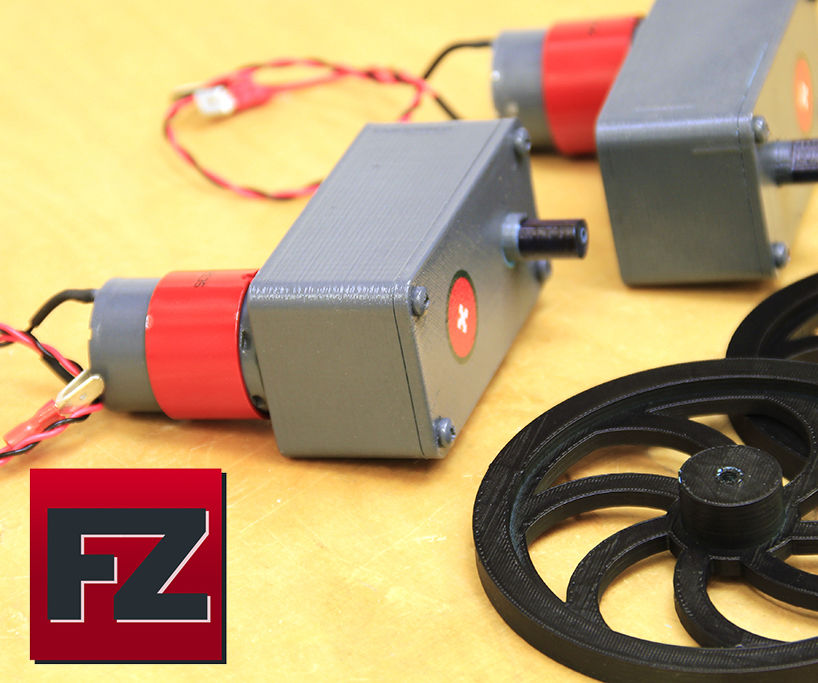
Here is a diagram of the actual gear attached to the DC motor

Unlike servo motors, the shaft has length, so it is good that the gear is fixed to some extent perpendicular to the gear when the gear is mounted including that part.
When a gear is directly mounted on a servomotor as shown below, there is no axial fixation of the gear, so unless it is separately fixed, the gear has so far been dislodged from the servomotor in the axial direction of the gear when linear motion is attempted with a rack and pinion mechanism.
Create code for 3 rotations up and down
The final code requires the dc motor to rotate up and down so that the lower lip moves up and down only while the cat is speaking, but we created a code for three rotations up and down in a temporary placement.
Unlike servomotors, the angle of rotation cannot be controlled, so the time to rotate must be adjusted (the code below assumes 0.5 seconds for now).
The rotation speed is set between 0-255 by the second argument of the analogWrite function (duty cycle of the PWM signal of the motor) in the startMortor() function.
In this case, the rotation speed is fixed, so the number is directly written in the second argument.
#include <Arduino.h>

#define MOTOR_PIN1 12
#define MOTOR_PIN2 14
#define SPEED_PIN 13
#define BUTTON_PIN 15

bool isMoving = false;
bool lastButtonState = LOW;
int moveCount = 0;
bool direction = true;
unsigned long lastUpdate;
unsigned long moveDuration = 500;

void stopMotor() {
  isMoving = false;
  digitalWrite(MOTOR_PIN1, LOW);
  digitalWrite(MOTOR_PIN2, LOW);
  analogWrite(SPEED_PIN, 0);
}

void startMotor() {
  isMoving = true;
  if (direction) {
    digitalWrite(MOTOR_PIN1, HIGH);
    digitalWrite(MOTOR_PIN2, LOW);
  } else {
    digitalWrite(MOTOR_PIN1, LOW);
    digitalWrite(MOTOR_PIN2, HIGH);
  }
  analogWrite(SPEED_PIN, 255);
  lastUpdate = millis();
}

void setup() {
  Serial.begin(115200);
  pinMode(MOTOR_PIN1, OUTPUT);
  pinMode(MOTOR_PIN2, OUTPUT);
  pinMode(SPEED_PIN, OUTPUT);
  pinMode(BUTTON_PIN, INPUT_PULLUP);
  stopMotor();
}

void loop() {
  bool currentButtonState = digitalRead(BUTTON_PIN);

  if (lastButtonState == HIGH && currentButtonState == LOW) {
    if (!isMoving) {
      startMotor();
    }
    delay(50);
  }

  if (isMoving) {
    if (millis() - lastUpdate > moveDuration) {
      direction = !direction;
      moveCount++;
      if (moveCount >= 6) {
        stopMotor();
        moveCount = 0;
      } else {
        startMotor();
      }
    }
  }

  lastButtonState = currentButtonState;
}
C-clamp creation
A C-shaped clamp is created on the opposite side of the rack from where it meets the gear to hold the hair clip elastic during the vertical movement.
I was concerned that the part being held in place might be visible from the front and look uncomfortable as a mouth, but when I actually created it, it hardly bothered me. Plus, even with a C-shaped clamp of about 2 mm in width, the rubber holding force was stronger than I had imagined, so I was pleased that it did not seem to come off even after moving it up and down many times.


Rack and pinion moves by itself, but not when rubber is attached
When set to duty cycle 168, the rack-and-pinion mechanism alone worked well enough.
The equivalent of a lower lip, just with a hair clip elastic, worked fine.
However, if one of the lips is fixed in the depth direction through the hole, the motor does not have enough drive to move. Greasing the rack-pinion to reduce friction is one thing, but what else should I do?
The servo is set to a smaller rotational angle still, but within the set angle range, the servo is moving with the pinion mechanism even with the string attached, so does the servo have more driving force?
As for the noise, we have not yet been able to run the servo motor with rubber on it, so we have not been able to make an accurate comparison, but it seems that the dc motor is quieter than the servo motor even when run at maximum speed (duty cycle 255). So, if possible, I would like to switch to DC motors.


コメント